Creating Basic Revit Families (Step-by-Step)
Creating Basic Revit Families is the foundation of every successful BIM project. Whether you are working in Autodesk Revit for architectural, structural, or MEP design, mastering the process of creating basic families is one of the most valuable skills you can develop to improve accuracy, flexibility, and workflow efficiency.
When I first started working with Revit families, I relied heavily on pre-made content. But soon I realized that professional projects demand customization. Clients want specific dimensions, manufacturers provide unique specifications, and site conditions rarely match default content. That’s when learning to create basic families became essential.
In this detailed guide, I will walk you step-by-step through creating basic Revit families in a simple and practical way. No complicated theory — just clear, real-world steps you can follow.
What Is a Revit Family?
In Revit, a family is a group of elements with a common set of properties (parameters) and a related graphical representation.
Examples include:
-
Doors
-
Windows
-
Furniture
-
Lighting fixtures
-
Plumbing fixtures
-
Generic models
Every object you place in a Revit project belongs to a family.
There are three main types:
-
System Families (Walls, Floors, Roofs)
-
Loadable Families (Doors, Windows, Furniture)
-
In-Place Families (Custom elements created inside a project)
In this article, we’ll focus on Loadable Families, which you create in the Family Editor and load into projects.
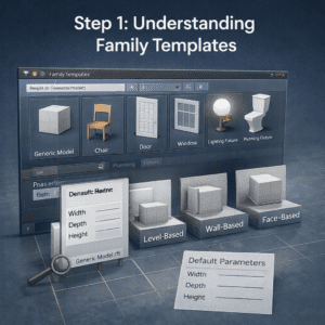
Step 1: Understanding Family Templates
Before creating a family, you must select the correct template.
Why Templates Matter
Templates define:
-
Category (Door, Window, Furniture, etc.)
-
Hosting behavior (Wall-based, Face-based, Level-based)
-
Default parameters
-
Family behavior
If you choose the wrong template, your family may not behave properly inside a project.
How to Start a New Family
-
Open Revit
-
Click File → New → Family
-
Select a template
For beginners, start with:
-
Generic Model.rft
-
Furniture.rft
These are simple and flexible.
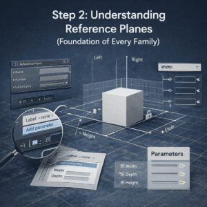
Step 2: Understanding Reference Planes (Foundation of Every Family)
Reference planes are the skeleton of your family.
Without proper reference planes, your family will not flex correctly when dimensions change.
Why Reference Planes Are Important
They help you:
-
Control geometry
-
Add dimensions
-
Create parametric behavior
-
Lock geometry properly
Creating Basic Reference Planes
Inside the Family Editor:
-
Go to Create Tab
-
Select Reference Plane
-
Draw vertical and horizontal planes
Create:
-
Left
-
Right
-
Front
-
Back
Then add dimensions between them.
Converting Dimensions into Parameters
-
Select the dimension
-
Click Label
-
Choose Add Parameter
-
Name it (Example: Width, Depth)
Now your family becomes parametric.
This is the most important step in professional family creation.
Step 3: Creating Basic Geometry (Extrusion)
Now that reference planes and parameters are ready, we create geometry.
What Is Extrusion?
Extrusion is the most basic form in Revit. It allows you to create 3D shapes by drawing a 2D profile and giving it height.
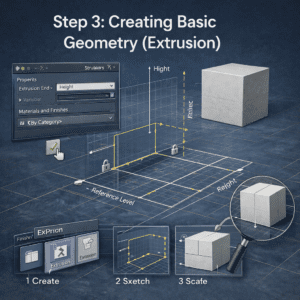
Creating an Extrusion Step-by-Step
-
Go to Create Tab
-
Click Extrusion
-
Draw a rectangle (aligned with reference planes)
-
Finish the sketch
Now set the extrusion height:
-
Align bottom to Reference Level
-
Set top with a parameter (Height)
Locking Geometry Properly
Use Align Tool (AL):
-
Align geometry to reference plane
-
Click the lock symbol
This ensures that when Width or Depth changes, the geometry adjusts automatically.
If you forget locking, your family will break later.
Step 4: Adding Parameters (Making It Smart)
A basic model is good. A parametric model is powerful.
Types of Parameters
There are two main types:
1. Type Parameters
These affect all instances of the family type.
Example:
-
Door width for all “900mm Door” types
2. Instance Parameters
These can vary individually.
Example:
-
Mark number
-
Installation height
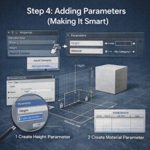
Creating a Height Parameter
-
Select extrusion
-
Go to Properties
-
Click small box beside dimension
-
Add parameter → Name: Height
-
Set as Type Parameter
Now test it:
-
Click Family Types
-
Change Height
-
Click Apply
If everything moves correctly, you did it right.
Step 5: Adding Materials
Professional families must allow material control.
Why Material Parameters Are Important
They allow users to:
-
Change finishes
-
Render correctly
-
Control schedules
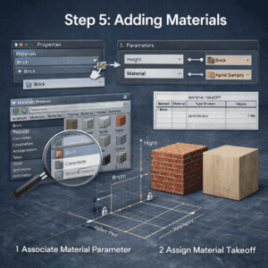
Adding a Material Parameter
-
Select geometry
-
In Properties → Material
-
Click small box
-
Add Parameter
-
Name: Material
-
Set Type Parameter
Now materials can be changed from project level.
Step 6: Testing the Family (Flexing)
This step separates beginners from professionals.
What Is Flexing?
Flexing means testing parameters by changing values to ensure geometry behaves correctly.
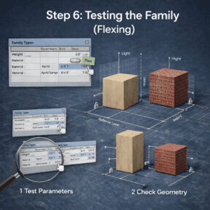
How to Flex Properly
-
Open Family Types
-
Change Width (small value)
-
Change Width (large value)
-
Change Height
-
Click Apply each time
Watch for:
-
Geometry breaking
-
Misalignment
-
Errors
If something breaks, check:
-
Are reference planes locked?
-
Are dimensions labeled?
-
Is geometry aligned?
Always flex before loading into a project.
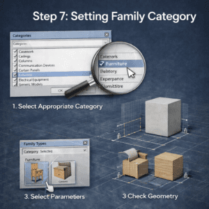
Step 7: Setting Family Category
Your family must belong to the correct category.
How to Set Category
-
Click Family Category and Parameters
-
Select appropriate category
Example:
-
Furniture
-
Plumbing Fixture
-
Lighting Fixture
-
Generic Model
Category affects:
-
Visibility
-
Scheduling
-
Hosting behavior
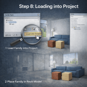
Step 8: Loading into Project
Now it’s time to test inside a real project.
-
Click Load into Project
-
Place the family
-
Change types
-
Modify dimensions
If it works smoothly, congratulations — you created your first proper basic family.
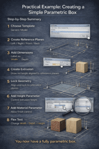
Practical Example: Creating a Simple Parametric Box
Let’s summarize everything with a simple example.
Step-by-Step Summary
Step 1: Choose Template
Generic Model
Step 2: Create Reference Planes
Left / Right / Front / Back
Step 3: Add Dimensions
Label as:
-
Width
-
Depth
Step 4: Create Extrusion
Draw rectangle aligned to reference planes
Step 5: Lock Geometry
Align and lock to reference planes
Step 6: Add Height Parameter
Control extrusion height
Step 7: Add Material Parameter
Allow finish control
Step 8: Flex Test
Change Width / Depth / Height
You now have a fully parametric box.
Common Mistakes Beginners Make
1. Modeling Before Adding Reference Planes
Always start with reference planes. Geometry comes later.
2. Not Locking Geometry
If you don’t lock elements, parameters will fail.
3. Not Flexing Early
Flex after every major step.
4. Overcomplicating the Family
Start simple. Master basics before creating complex parametric systems.
Professional Tips for Better Family Creation
Keep It Clean
-
Use proper naming conventions
-
Avoid unnecessary reference planes
-
Keep constraints minimal
Use Subcategories
This helps with visibility control in projects.
Keep File Size Small
Avoid:
-
Too many nested families
-
Unnecessary details
-
Imported CAD files
Always Think Parametric
Ask yourself:
-
Will this dimension ever change?
-
Should this be instance-based?
-
Should this be type-based?
When to Use Nested Families
Once you master basics, you can start nesting families.
Example:
-
Table family containing chair family
-
Electrical panel containing breakers
Nested families increase flexibility but also complexity.
Start only after you fully understand basic family creation.
Final Thoughts
Creating basic Revit families is not difficult — but it requires discipline.
The key principles are:
-
Start with reference planes
-
Add parameters early
-
Lock geometry properly
-
Flex constantly
-
Keep families clean and lightweight
If you practice creating simple parametric objects every day — boxes, cabinets, panels, supports — within a few weeks you’ll develop strong control over family behavior.
And once you control families, you control your BIM workflow.
That’s when you move from being a Revit user to becoming a true Revit professional.