How to Create Sections & Callouts Properly
Understanding How to Create Sections & Callouts Properly is one of the most essential skills in architectural drafting and BIM documentation. Floor plans alone cannot fully explain a building’s design intent. To clearly communicate vertical relationships, detailed construction elements, and complex connections, you must know how to create sections and callouts properly with accurate placement and clear detailing.
This guide explains what sections and callouts are, why they matter, and how to create them correctly using professional standards. Whether you are a beginner or an experienced Revit user, mastering this topic will significantly improve your drawing quality.
Understanding Sections and Callouts
Before learning how to create them, you must clearly understand their purpose.
What Is a Section?
A section is a vertical cut through a building or object. Imagine slicing the building from top to bottom and looking directly at the cut surface. A section shows elements that cannot be fully understood in a floor plan, such as:
-
Floor-to-floor heights
-
Ceiling levels
-
Structural beams and slabs
-
Wall assemblies
-
Window head heights
-
Stair relationships
Sections reveal how different components connect vertically.
What Is a Callout?
A callout is an enlarged view of a specific portion of a plan, section, or elevation. It is used when an area requires more detail than the original scale can provide.
Callouts are typically used for:
-
Bathroom layouts
-
Kitchen details
-
Staircase areas
-
Wall junctions
-
Door and window details
Callouts improve clarity by zooming in on important construction areas.
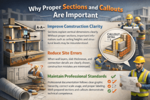
Why Proper Sections and Callouts Are Important
Improve Construction Clarity
Sections explain vertical dimensions clearly. Without proper sections, important information such as ceiling heights and structural levels may be misunderstood.
Reduce Site Errors
When wall layers, slab thicknesses, and connection details are clearly shown, construction mistakes are minimized.
Maintain Professional Standards
Professional documentation follows clear graphic hierarchy, correct scale usage, and proper labeling. Well-prepared sections and callouts demonstrate technical competence.
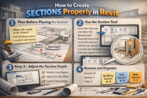
How to Create Sections Properly in Revit
If you are using Revit, sections are dynamic views linked to the model. Any change in the model automatically updates the section.
Step 1 – Plan Before Placing the Section
Before placing a section, ask yourself:
-
What information needs to be shown?
-
Is this a full building section or a localized wall section?
-
Does it cut through important elements like stairs or openings?
Never place a section randomly. It must serve a clear purpose.
Step 2 – Use the Section Tool
Go to the View tab and select the Section tool. Draw the section line across the area you want to cut. Ensure it crosses key elements that must appear in the view.
The direction of the section arrow matters. Make sure it faces the area you want to display.
Step 3 – Adjust the Section Depth
After placing the section:
-
Modify the crop region
-
Adjust the far clip offset
-
Control view depth
If the section is too deep, it may show unnecessary background elements. If it is too shallow, critical information might be hidden.
Step 4 – Rename and Organize
Avoid default names like “Section 1” or “Copy 2.” Use meaningful names such as:
-
Building Section A-A
-
Stair Section B-B
-
Wall Section C-C
Clear naming improves project organization.
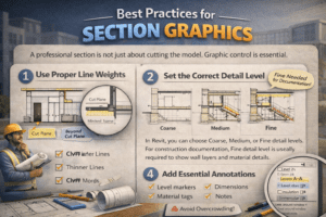
Best Practices for Section Graphics
A professional section is not just about cutting the model. Graphic control is essential.
Use Proper Line Weights
Cut elements should have thicker lines. Elements beyond the cut plane should have thinner lines. This creates visual depth and improves readability.
Set the Correct Detail Level
In Revit, you can choose Coarse, Medium, or Fine detail levels. For construction documentation, Fine detail level is usually required to show wall layers and material details.
Add Essential Annotations
Include:
-
Level markers
-
Dimensions
-
Material tags
-
Notes
However, avoid overcrowding. Keep the drawing clean and readable.
How to Create Callouts Properly in Revit
Callouts allow you to zoom into a specific area for detailed explanation.
Step 1 – Select the Callout Tool
From the View tab, choose the Callout tool. Draw a boundary around the area that needs enlargement.
Step 2 – Set the Correct Scale
Callouts should always be at a larger scale than the original view. Common scales include:
-
1:20
-
1:10
-
1:5
The purpose is to show more detail, so avoid using the same scale as the main plan.
Step 3 – Adjust Visibility Settings
Control:
-
Detail level
-
Visibility/graphics overrides
-
Hidden lines
Make sure all necessary elements are visible and clearly represented.
Step 4 – Add Detail Components
Enhance the callout by adding:
-
Insulation layers
-
Fixings
-
Hardware
-
Detailed notes
-
Dimensions
Callouts should communicate construction logic clearly.

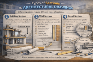
Types of Sections in Architectural Drawings
Different projects require different types of sections.
Building Section
A building section cuts through the entire structure from foundation to roof. It shows:
-
Structural system
-
Floor levels
-
Ceiling heights
-
Roof structure
This type of section explains the overall vertical organization of the building.
Wall Section
A wall section focuses on the construction of a specific wall assembly. It typically shows:
-
Wall layers
-
Slab connection
-
Insulation
-
Exterior and interior finishes
Wall sections are usually drawn at larger scales like 1:10 or 1:5.
Detail Section
Detail sections zoom into specific connections such as:
-
Stair joints
-
Window sill details
-
Roof parapets
-
Expansion joints
These sections require precision and technical accuracy.
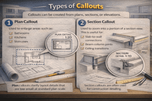
Types of Callouts
Callouts can be created from plans, sections, or elevations.
Plan Callout
Used to enlarge areas such as:
-
Bathrooms
-
Kitchens
-
Staircases
Plan callouts clarify layout details that are too small at standard plan scale.
Section Callout
Used to zoom into a portion of a section view. This is useful for:
-
Slab-to-wall connections
-
Beam-column joints
-
Ceiling transitions
Section callouts are often used for construction detailing.
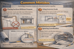
Common Mistakes to Avoid
Avoiding mistakes improves documentation quality.
Placing Sections Without Purpose
Every section must provide new information. If it does not add value, it is unnecessary.
Using Incorrect Scale
A callout at the same scale as the plan defeats the purpose of enlargement.
Overcrowding with Notes
Too many annotations reduce clarity. Keep notes concise and relevant.
Ignoring Coordination
Always check coordination between:
-
Architectural model
-
Structural model
-
MEP model
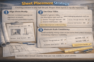
Sections often reveal clashes that are not visible in plan views.
Sheet Placement Strategy
Creating a section is only half the job. Proper sheet layout is equally important.
Align Views Neatly
Maintain consistent spacing and alignment on sheets. This improves presentation quality.
Use Clear Titles
Instead of generic titles, use descriptive ones such as:
-
Section Through Staircase – S1
-
Exterior Wall Section – W1
Clear titles improve understanding.
Maintain Scale Consistency
Avoid randomly mixing scales on the same sheet unless necessary. Consistency improves readability.
Advanced Professional Tips
Use Reference Sections
If a section already exists on another sheet, use reference sections instead of duplicating views. This keeps documentation organized.
Apply View Templates
View templates help control:
-
Line weights
-
Detail level
-
Visibility settings
Using templates ensures consistency across the project.
Utilize Scope Boxes
Scope boxes can control multiple section extents simultaneously, which is useful for large projects.
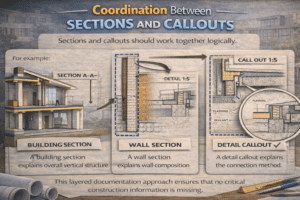
Coordination Between Sections and Callouts
Sections and callouts should work together logically.
For example:
-
A building section explains overall vertical structure.
-
A wall section explains wall composition.
-
A detail callout explains the connection method.
This layered documentation approach ensures that no critical construction information is missing.
Final Thoughts
Creating sections and callouts properly is not just a software skill. It is a communication skill. Clear documentation reduces construction errors, improves coordination, and reflects professionalism.
Always remember:
-
Plan before placing
-
Use correct scale
-
Control graphics
-
Avoid clutter
-
Maintain coordination
When sections and callouts are created thoughtfully and organized professionally, your drawings become powerful communication tools. Strong documentation builds confidence among clients, consultants, and contractors.
Mastering sections and callouts will elevate your architectural and BIM documentation to a professional level.