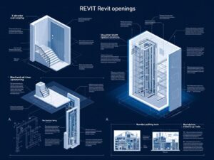
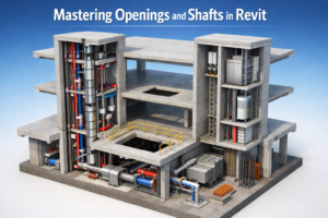
Mastering Openings and Shafts in Revit
A Complete Guide to Creating Floor Openings for Stairs, Elevators, and MEP Systems
When working on a building project in Revit, mastering openings and shafts in Revit is a key part of creating a well-coordinated model. From staircases and elevator shafts to duct chases and plumbing risers, every multi-story building depends on correctly placed vertical openings to allow people and building services to move smoothly between floors.
At first glance, openings may seem simple—just empty spaces cut through floors or walls. However, anyone with real BIM experience knows they can quickly become a source of coordination issues. Misaligned openings, missing shafts, or unclear boundaries often lead to confusion during documentation and, in many cases, clashes between architectural, structural, and MEP models.
This is why understanding how openings and shafts work in Revit is so important. In this guide, we’ll walk through the essentials, starting with how to create openings for stairs and elevators and moving into best practices for editing boundaries and coordinating across disciplines. By the end, you’ll have a clearer, more confident approach to handling vertical openings in your Revit projects.
The Role of Openings and Shafts in Building Design
Before diving into the “how,” it helps to understand what openings represent in a building model. They are not just voids; they are coordinated zones that allow systems or circulation elements to pass vertically.
Common Types of Openings
- Stair openings — allow the stair flights and landings to pass between levels
- Elevator shafts — accommodate the elevator car, rails, pit, and overhead equipment
- Mechanical riser shafts — carry ductwork, piping, electrical conduits, and fire protection systems
- Atrium openings — large voids that extend through multiple stories
- Service chases — smaller openings for plumbing stacks or cable runs
These spaces are essential architectural and engineering components, and Revit provides tools that allow designers to model them accurately.
Creating Openings for Stairs
Stair openings are among the most common and straightforward floor openings you’ll create in a building model.
Method 1: Using the Floor Opening Tool
This approach is simple and works best when the stair geometry is already placed.
Steps:
- Select the Opening > By Face tool or Shaft Opening depending on the complexity.
- Click on the floor face where the opening is needed.
- Sketch the opening boundary following the perimeter of the stair.
- Finish the sketch.
Revit cuts the floor based on the shape you define.
Why Sketching Matters
The opening boundary must follow the stair geometry precisely. If the stair receives a change—width, landing depth, or rotation—the opening must be adjusted manually.
This is why some firms link stair families with openings as grouped components. It ensures modifications stay coordinated.
Method 2: Using the Shaft Tool for Multi-Level Staircases
For staircases that span multiple levels, a shaft opening is more efficient than separate openings on each floor.
Advantages:
- One sketch controls the opening for all levels
- Easy to adjust when the staircase shape changes
- Automatically applies the void to each floor it touches
This method is ideal for large public staircases or open stairwells.
Creating Openings for Elevators
Unlike stairs, elevator openings are far more consistent in size and easier to standardize. Most elevator manufacturers provide exact shaft dimensions, making the process even smoother.
Using Shaft Openings for Elevators
- Choose Shaft Opening from the Architecture tab.
- Sketch the rectangular boundary of the elevator shaft.
- Set the base constraint (often the lowest level or pit).
- Set the top constraint (often the top of the elevator overrun or machine room level).
- Finish the sketch.
The shaft automatically penetrates through all floors between the base and top constraints.
Important Considerations for Elevator Shafts
- Pit depth: Elevators require a pit below the lowest landing floor.
- Overhead clearance: Headroom above the top landing must be accounted for.
- Structural walls: The shaft typically requires reinforced concrete walls.
- Openings for mechanical rooms: Some elevators require space for control equipment.
Revit makes it easy to coordinate all these needs through elevations and sections once the shaft is in place.
Creating Openings for Ducts and MEP Systems
MEP systems often require smaller, more precise openings compared to stairs and elevators. These openings need to be coordinated closely with MEP engineers to ensure that ducts and piping can pass through floors without clashes.
Option 1: Opening by Face
This tool allows you to define an opening directly on a selected face of a floor or ceiling.
How it works:
- Select the Opening > By Face tool.
- Pick the underside of the floor.
- Sketch the opening shape (typically rectangular for ducts).
- Finish the model.
This method is best for individual penetrations created after MEP routing is complete.
Option 2: Shaft Openings for Vertical MEP Risers
For large duct risers or plumbing stacks, a shaft opening provides clear boundaries and applies across multiple levels.
Example uses:
- Vertical duct shafts
- Plumbing riser rooms
- Fire protection risers
- Electrical riser chases
This method keeps vertical MEP routes clean and coordinated.
Managing Multi-Level Shaft Openings in Revit
Shaft openings are more flexible than they first appear. When mastering openings and shafts in Revit, it’s important to understand that shafts are not just for elevators—they are ideal for any multi-floor void that must stay aligned and consistent across levels.
Key Characteristics of Shaft Openings
- They pass through multiple floors automatically
- They allow boundary sketches of any shape
- They can cut floors, ceilings, and roofs simultaneously
- Their shape can be modified at any time
- They show up in plan, 3D, section, and coordination views
Shaft openings are the backbone of vertical coordination in BIM projects.
Where Shaft Openings Are Most Useful
- Hotels with stacked mechanical risers
- Office buildings with elevator cores
- Hospitals with stacked utilities
- High-rise buildings with mechanical floors
- Multi-level shopping malls with escalators
Any building with vertical circulation or utilities will depend on accurate shafts.
Boundary Editing: A Crucial Skill for Cleanup and Coordination
Boundary editing is the process of modifying the perimeter of an opening or shaft after it has been created.
What You Can Adjust in Boundary Editing
- Shape of the opening (rectangle, circle, polygon)
- Size and position
- Alignment with stairs, walls, or duct routing
- Relationship to grids and reference planes
Revit allows a high degree of flexibility in boundary editing, but it requires careful attention to avoid disrupting other elements.
Best Practices for Editing Boundaries
-
Use Reference Planes for Accuracy
Sketching freehand leads to misalignment. Set reference planes along the edges of stairs, risers, or elevator walls before modifying the boundary.
-
Lock Boundaries When Needed
Locking lines to reference planes ensures the opening moves automatically when related geometry changes.
-
Avoid Overlapping Boundaries
Overlapping lines or irregular shapes may cause errors or incomplete cuts.
-
Coordinate With Other Disciplines
Many openings affect both architecture and structure. Use shared parameters or color-coded views to keep everyone aligned.
-
Use 3D Views to Check Your Work
Plan views may miss subtle misalignments. Switching to 3D ensures the void cuts cleanly through all floors.
Common Mistakes to Avoid
Even experienced Revit users run into issues when dealing with openings and shafts. Here are some of the most common pitfalls.
-
Misaligned Floor Openings
If the opening doesn’t match the stair or duct geometry, contractors will face headaches on site. Always double-check alignment in section views.
-
Duplicate Openings on Multiple Floors
When using floor-based openings instead of shafts, users sometimes create openings on each level manually. This leads to:
- inconsistencies
- difficulty editing
- potential for missed floors
A shaft opening eliminates this risk.
-
Forgetting to Adjust Base and Top Constraints
Incorrect constraints can cause shafts to stop too early or extend further than intended.
-
Editing the Wrong Boundary
It is easy to modify the boundary for the wrong element, especially when multiple openings overlap.
-
Ignoring Structural Requirements
Architects must coordinate opening sizes with structural engineers. A misplaced or undersized opening can cause major redesigns.

Coordinating Openings Across Disciplines
A well-coordinated model prevents clashes and ensures that all openings support the needs of the entire team.
Architects should:
- Define staircase and elevator openings early
- Coordinate finish floor levels around openings
- Communicate changes quickly
Structural engineers should:
- Reinforce floor openings correctly
- Check that slab edges and beams align with opening boundaries
MEP engineers should:
- Confirm duct and pipe sizes early
- Verify that risers align between levels
- Request adjustments when routing changes
Collaboration tools like Revit’s Worksets, Shared Coordinates, and Interference Check help keep everyone aligned.
Conclusion: Openings and Shafts Are Small Details That Make a Big Difference
Openings may not be as visually striking as bold facades or polished interiors, but they are critical to how a building actually works. In Revit, mastering openings and shafts in Revit means knowing how to correctly create stair openings, elevator shafts, duct penetrations, and multi-story voids to maintain a clean and coordinated BIM model.
By understanding the different opening types, refining boundary editing skills, and coordinating closely with architectural, structural, and MEP teams, you can avoid costly errors and keep your Revit model accurate and reliable from start to finish.