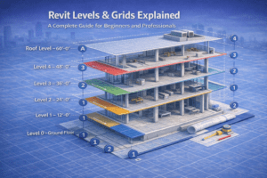
Revit Levels & Grids Explained: A Complete Guide for Beginners and Professionals
When starting any Revit project, two elements quietly control the entire model: Levels and Grids. Although they appear simple at first glance, incorrect setup can create long-term problems. As a result, even skilled modelers often face rework and coordination issues. In professional BIM workflows, levels and grids act as the backbone of accurate modeling, documentation, and teamwork.
This guide explains Revit Levels and Grids in detail. Along the way, you’ll learn what they are, how they function, and how to apply them correctly in real-world projects.
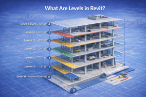
What Are Levels in Revit?
Levels in Revit define the vertical heights or story elevations of a building. In simple terms, they control where floors, roofs, ceilings, and similar elements are placed. Instead of being just visual lines, levels serve as intelligent references that guide the entire model.
More importantly, levels are data-driven objects. Because of this, they directly influence how elements behave when changes occur.
Why Levels Matter
Levels play a critical role in Revit projects for several reasons:
-
They host floors, roofs, and ceilings
-
They define the top and base constraints of walls
-
They generate floor plan and ceiling plan views
-
They control vertical coordination across disciplines
Therefore, incorrect levels can easily disrupt the entire project structure.
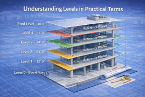
Understanding Levels in Practical Terms
Levels vs AutoCAD Layers
In AutoCAD, layers mainly control visibility. However, Revit levels behave very differently. Instead of being passive, levels actively control geometry and relationships.
For example, when a level elevation changes, all attached elements automatically update. As a result, levels must be planned carefully before modeling begins.
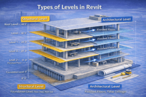
Types of Levels in Revit
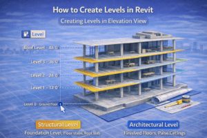
Structural Levels
Structural levels define the main construction heights, such as:
-
Foundation level
-
Plinth or base level
-
Typical floor levels
-
Roof slab level
Because structural drawings rely on precision, these levels must match engineering documentation exactly.
Architectural Levels
Architectural levels, on the other hand, often represent finished conditions. These may include:
-
Finished floor levels (FFL)
-
False ceiling levels
-
Mezzanine or split-floor levels
Although architectural levels may differ slightly from structural ones, they still require proper coordination.
How to Create Levels in Revit
Creating Levels in Elevation View
Levels can only be created in Elevation or Section views, not in plans.
To do this correctly:
-
Open an elevation or section view
-
Activate the Level tool
-
Draw a horizontal level line
-
Assign the correct elevation value
Afterward, Revit can automatically generate corresponding plan views if enabled.
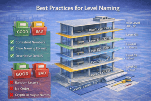
Best Practices for Level Naming (H3)
Clear naming improves coordination and reduces confusion later.
Recommended examples:
-
Level 0 – Ground Floor
-
Level 1 – First Floor
-
Level 2 – Second Floor
-
Roof Level
On the other hand, avoid unclear names such as:
-
Test Level
-
Copy 1
-
Floor A
Consistent naming ensures everyone understands the model instantly.
Common Level Mistakes to Avoid
Creating Levels After Modeling
One of the most frequent mistakes is adjusting levels after modeling has already started. Unfortunately, this leads to walls detaching, floors shifting, and views becoming incorrect. Therefore, all primary levels should be finalized before placing major elements.
Using Too Many Levels
Similarly, creating unnecessary levels often causes confusion. While accuracy is important, excessive levels complicate coordination. Instead, create only the levels that serve a clear design or construction purpose.
What Are Grids in Revit?
Grids represent the horizontal and vertical axes of a building layout. They help align columns, walls, beams, and structural elements consistently throughout the project.
In addition, grids are essential for:
-
Structural coordination
-
Clear dimensioning
-
Contractor communication
-
Accurate shop drawings
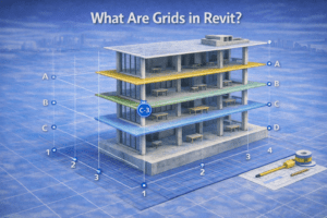
How Grids Work in Revit
Unlike physical elements, grids are datum references. They do not appear in 3D views; however, they control alignment across all plans, sections, and elevations.
Moreover, when elements are locked to grids, any grid movement updates those elements automatically. This behavior greatly improves consistency.
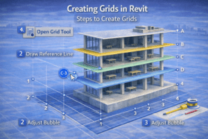
Creating Grids in Revit
Steps to Create Grids
To create grids efficiently:
-
Open a floor plan view
-
Select the Grid tool
-
Draw vertical and horizontal grid lines
-
Assign proper names
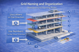
Typically, Revit uses numbers in one direction and letters in the other.
Grid Naming and Organization
Standard Grid Naming Rules (H3)
To maintain clarity:
-
Use numbers for one axis
-
Use letters for the perpendicular axis
-
Keep spacing logical and uniform
For example:
-
Vertical grids: 1, 2, 3, 4
-
Horizontal grids: A, B, C, D
This approach keeps drawings easy to read.
Avoid Renaming Grids Mid-Project
Once documentation begins, grid names should remain unchanged. Otherwise, renaming may cause drawing mismatches and site confusion. Therefore, finalize grid names early in the project.
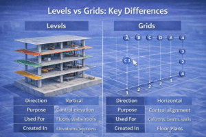
Levels vs Grids: Key Differences
| Feature | Levels | Grids |
|---|---|---|
| Direction | Vertical | Horizontal |
| Purpose | Control elevation | Control alignment |
| Used For | Floors, walls, roofs | Columns, beams, walls |
| Created In | Elevations/Sections | Floor Plans |
Clearly, both elements serve different but equally important roles.
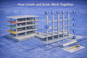
How Levels and Grids Work Together
A successful Revit model depends on strong coordination between levels and grids. For instance, columns align to grids while extending between defined levels. At the same time, beams sit at grid intersections and floors remain hosted to correct elevations.
As a result, errors in either system often lead to coordination failures.
Advanced Level Tips for Professionals
Split Levels and Multi-Level Floors (H4)
For split-level buildings, it is best to:
-
Create dedicated levels for each height change
-
Avoid hosting elements to incorrect reference levels
-
Verify relationships using section views
This method ensures vertical accuracy throughout the model.
Linked Models and Shared Levels
In multi-discipline projects, shared levels are critical. Therefore:
-
Match level names across linked models
-
Avoid duplicate or offset levels
-
Use shared coordinates
Doing so improves collaboration between architectural, structural, and MEP teams.
Advanced Grid Tips
Using Grids for Wall Alignment
Although grids are often associated with structure, they are also useful for architectural alignment. For example, core walls, shafts, and repetitive layouts benefit greatly from grid-based alignment.
Grid Visibility Control
Not all views need visible grids. Consequently:
-
Show grids in structural plans
-
Hide grids in presentation drawings
-
Adjust grid extents per view
This keeps drawings clean and professional.
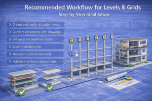
Recommended Workflow for Levels & Grids
Step-by-Step Ideal Setup
To avoid rework, follow this sequence:
-
Create and verify all major levels
-
Confirm elevations with drawings
-
Set up grids based on layout
-
Lock finalized grids
-
Model structural elements
-
Add architectural components
As a result, modeling becomes faster and more reliable.
Final Thoughts
Levels and grids may seem basic, yet they form the foundation of every successful Revit project. When set up correctly, they lead to cleaner models, faster revisions, and smoother coordination.
Before placing your first wall or column, invest time in proper level and grid planning. In the long run, this single step can define the quality of your entire BIM workflow.