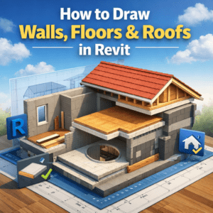
How to Draw Walls Floors & Roofs in Revit
Revit is not just a drafting tool—it’s a full Building Information Modeling (BIM) platform. When learning How to Draw Walls, Floors & Roofs in Revit, you’re not simply sketching lines or shapes; you’re creating intelligent building elements that understand height, thickness, materials, levels, and their relationships with other components.
If you’re new to Revit—or even if you’ve been using it for a while—getting these basics right will save you hours of rework later. In this guide, we’ll walk step by step through how to draw walls, floors, and roofs in Revit, using a practical, real-world approach rather than textbook theory.
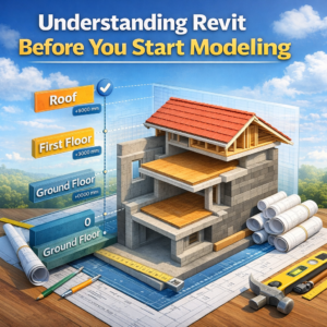
Understanding Revit Before You Start Modeling
Before drawing anything, it’s important to understand one core idea: Revit is level-based. Almost everything you model depends on levels.
Why Levels Matter in Revit
Walls, floors, and roofs all reference levels for their base, top, or height. If your levels are wrong, your entire model will feel broken.
Best Practice for Levels
-
Create all main levels first (Ground Floor, First Floor, Roof, etc.)
-
Verify elevations using architectural drawings
-
Rename levels clearly (avoid default names like “Level 1” if possible)
Once levels are set correctly, modeling becomes smooth and predictable.
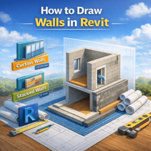
How to Draw Walls in Revit
Walls are usually the first elements you model in any Revit project. They define spaces, support floors and roofs, and control room boundaries.
Types of Walls in Revit
Revit offers several wall types, but the most common is Basic Wall.
Common Wall Categories
-
Basic Walls (most architectural walls)
-
Curtain Walls (glass façades)
-
Stacked Walls (rarely used, complex assemblies)
For most residential and commercial projects, Basic Walls are more than enough.
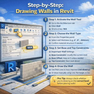
Step-by-Step: Drawing Walls in Revit
Step 1: Activate the Wall Tool
-
Go to the Architecture tab
-
Click Wall
-
Shortcut key: WA
Step 2: Choose the Wall Type
From the Properties panel:
-
Select wall thickness (e.g., 6″, 8″, 200mm)
-
Confirm material structure if needed
Step 3: Set Base and Top Constraints
This is where many beginners make mistakes.
Important Wall Settings
-
Base Constraint: Usually the current level
-
Base Offset: Keep at 0 unless needed
-
Top Constraint: Next level above
-
Unconnected Height: Use only if top constraint is not defined
Step 4: Draw the Wall
-
Use Pick Lines to trace imported CAD drawings
-
Or draw manually using Line, Rectangle, or Arc
💡 Pro Tip: Always check whether you’re drawing on the correct level before placing walls.
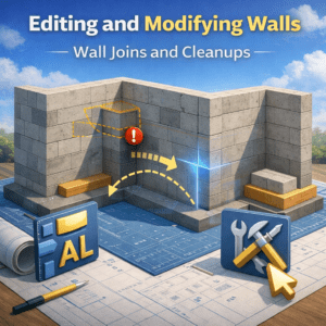
Editing and Modifying Walls
Wall Joins and Cleanups
Revit automatically cleans wall intersections, but sometimes manual adjustment is needed.
Useful Tools
-
Wall Joins
-
Trim/Extend
-
Align (AL)
Wall Openings
Doors and windows automatically cut walls when placed. For custom openings:
-
Use Wall Opening tool
-
Or model voids for complex cases
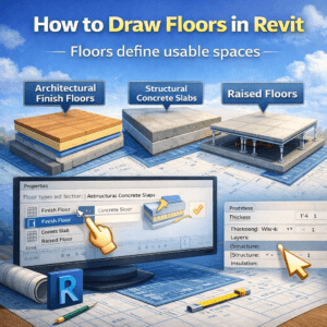
How to Draw Floors in Revit
Floors define usable spaces and structural slabs. In Revit, floors are sketch-based elements.
Understanding Floor Types
Before drawing a floor, you must choose the correct type.
Common Floor Types
-
Architectural Finish Floors
-
Structural Concrete Slabs
-
Raised Floors
Each floor type has:
-
Thickness
-
Layers (finish, structure, insulation)
-
Structural or non-structural behavior
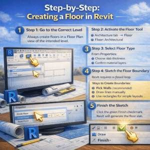
Step-by-Step: Creating a Floor in Revit
Step 1: Go to the Correct Level
Always create floors in a Floor Plan view of the intended level.
Step 2: Activate the Floor Tool
-
Architecture tab → Floor → Floor: Architectural
Step 3: Select Floor Type
From Properties:
-
Choose slab thickness
-
Confirm material layers
Step 4: Sketch the Floor Boundary
Revit requires a closed loop.
Ways to Create Boundaries
-
Pick Walls (recommended)
-
Draw lines manually
-
Use rectangles for simple layouts
⚠️ If the boundary is not closed, Revit will not let you finish the floor.
Step 5: Finish the Sketch
Click the green Finish checkmark. Revit will generate the floor slab.
Advanced Floor Tips
Floor Offsets
Use offsets when:
-
Finish floor is above structural slab
-
Different finishes exist in the same level
Openings in Floors
For stairs, shafts, or ducts:
-
Use Opening by Face
-
Or Shaft Opening for vertical penetrations
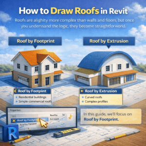
How to Draw Roofs in Revit
Roofs are slightly more complex than walls and floors, but once you understand the logic, they become straightforward.
Types of Roofs in Revit
Roof by Footprint
Most commonly used for:
-
Residential buildings
-
Simple commercial roofs
Roof by Extrusion
Used for:
-
Curved roofs
-
Complex profiles
In this guide, we’ll focus on Roof by Footprint.
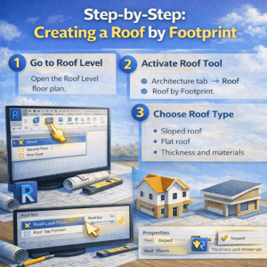
Step-by-Step: Creating a Roof by Footprint
Step 1: Go to Roof Level
Open the Roof Level floor plan.
Step 2: Activate Roof Tool
-
Architecture tab → Roof → Roof by Footprint
Step 3: Choose Roof Type
Select:
-
Sloped roof
-
Flat roof
-
Thickness and materials
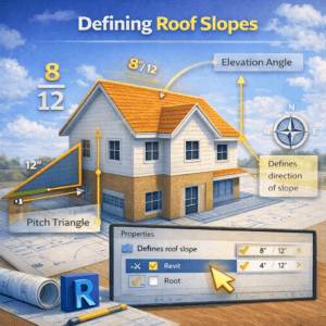
Defining Roof Slopes
This step defines the roof shape.
Slope Options
-
Defines Slope: Checked for sloping edges
-
Slope Value: e.g., 1:10, 2:12
Common Mistake
Beginners often apply slope to all edges, causing strange roof geometry.
💡 Tip: Usually, only two opposite edges define slope in pitched roofs.
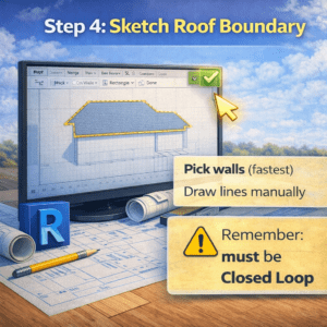
Step 4: Sketch Roof Boundary
Use:
-
Pick Walls (with overhang)
-
Draw lines manually
Make sure:
-
Boundary is closed
-
Overhang is consistent
Step 5: Finish Roof
Click Finish and switch to 3D view to verify the result.
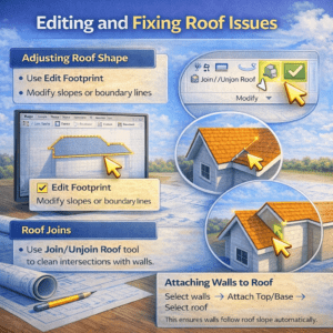
Editing and Fixing Roof Issues
Adjusting Roof Shape
-
Use Edit Footprint
-
Modify slopes or boundary lines
Roof Joins
Use Join/Unjoin Roof tool to clean intersections with walls.
Attaching Walls to Roof
Select walls → Attach Top/Base → Select roof
This ensures walls follow roof slope automatically.
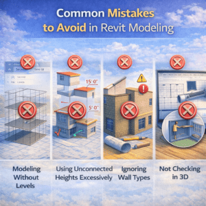
Common Mistakes to Avoid in Revit Modeling
Modeling Without Levels
Never start modeling before confirming levels.
Using Unconnected Heights Excessively
Top constraints are more reliable than manual heights.
Ignoring Wall Types
Wrong wall types can cause:
-
Incorrect quantities
-
Material takeoff errors
Not Checking in 3D
Always review walls, floors, and roofs in 3D view.
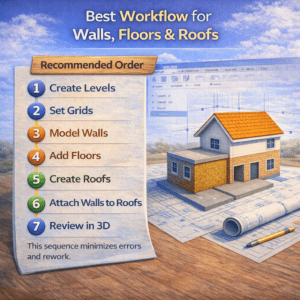
Best Workflow for Walls, Floors & Roofs
Recommended Order
-
Create Levels
-
Set Grids
-
Model Walls
-
Add Floors
-
Create Roofs
-
Attach Walls to Roofs
-
Review in 3D
This sequence minimizes errors and rework.
Final Thoughts
Learning how to draw walls, floors, and roofs in Revit is the foundation of every BIM project. Once these elements are modeled correctly, everything else—doors, windows, stairs, schedules, quantities—falls into place naturally.
Revit rewards patience and planning. Instead of rushing into modeling, take a few minutes to set levels, choose correct types, and understand constraints. Those small decisions make a huge difference in professional projects.
If you master these basics, you’re already ahead of many Revit users who struggle with broken models and constant revisions.