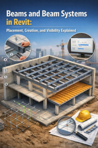
Beams and Beam Systems in Revit: Placement, Creation, and Visibility Explained
Beams and Beam Systems in Revit play a vital role in any building model, as they support loads, maintain structural stability, and ensure proper coordination between architectural, structural, and MEP disciplines. In a BIM environment, precise modeling goes beyond simply placing elements; it focuses on achieving clarity, seamless coordination, and construction-ready documentation.
This article provides a complete practical guide to beams and beam systems, focusing on beam placement on grids, beam system creation, and beam visibility and analytical settings. Whether you are a beginner or an intermediate Revit user, this guide will help you model beams efficiently and professionally using Autodesk Revit.
Understanding Beams and Beam Systems in Revit
Before diving into modeling techniques, it is important to understand how beams and beam systems function within a BIM workflow.
What Are Structural Beams?
Structural beams are horizontal load-bearing members that transfer loads from slabs, roofs, or walls to columns and foundations. In Revit, beams belong to the Structural Framing category and can be modeled individually or as part of a system.
What Is a Beam System?
Beam systems are commonly used in floor and roof framing. In addition, they are ideal for repetitive structural layouts and for supporting steel or concrete slab systems.
Beam systems save time, reduce manual errors, and maintain uniform spacing.
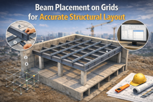
Beam Placement on Grids for Accurate Structural Layout
Beam placement on grids is one of the most reliable methods to achieve accurate and coordinated structural framing.
Why Place Beams on Grids?
Placing beams on grids ensures structural consistency and accurate load paths. Moreover, coordination with drawings and schedules becomes easier, and as a result, updates caused by grid changes can be managed more efficiently.
Using grids also helps maintain industry standards and improves clarity in construction documents.
Step-by-Step Beam Placement on Grids
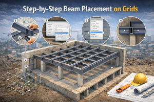
Step 1: Set Up Structural Grids
Before placing beams, ensure that grids are properly spaced and named according to project standards. Additionally, locking grids where required helps maintain alignment and prevents unintended changes during modeling.Well-defined grids form the backbone of a clean structural model.
Step 2: Activate Structural Framing Tool
Go to:
Structure → Beam
Choose the appropriate beam family such as:
-
Concrete rectangular beam
-
Steel I-beam or wide flange beam
-
Custom parametric beam
Aligning Beams with Grids
Snap and Alignment Best Practices
-
Use Snap to Grid Intersections
-
Verify beam justification (center, left, or right)
-
Confirm beam elevation level
Incorrect alignment can cause clashes with slabs or ceilings, so always check section views after placement.

Using Levels with Grid-Based Beam Placement
This approach ensures proper analytical connectivity. Moreover, elevations remain accurate, which ultimately results in clean and reliable structural schedules.Avoid placing beams “unconnected” unless required for special cases.
Beam System Creation for Efficient Framing Design
Beam system creation is one of the most powerful features for repetitive framing layouts.

When to Use Beam Systems
Beam systems are ideal for large floor areas where uniform spacing is required. For example, they work well when modeling steel or timber decking supports and when designing efficient slab support structures.
Instead of placing beams one by one, a beam system generates them automatically.
How to Create a Beam System
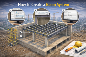
Step 1: Activate Beam System Tool
Navigate to:
Structure → Beam System
Select the appropriate beam family before drawing the system.
Step 2: Define the Beam System Boundary
Beam systems can be created using closed sketch boundaries or by selecting structural and architectural elements. In many cases, floors or roofs can also be used as hosts to simplify the framing process. Always ensure the boundary is clean and closed to avoid system errors.
Controlling Beam Layout Direction
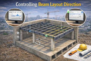
Beam Direction Settings
Beam direction defines how framing elements are oriented within a system. For instance, layouts may run parallel to grids, perpendicular to primary supports, or follow custom angles based on design requirements. Incorrect direction settings can lead to inefficient or unrealistic framing.
Adjusting Beam Spacing and Rules
Spacing rules can be controlled using fixed distances, a specified number of elements, or maximum spacing limits. This flexibility allows the model to match real-world structural standards and design codes. These parameters allow you to match real-world structural standards and design codes.
Advanced Beam System Creation Techniques

Editing Beam Systems After Creation
After creation, beam systems remain fully editable. For example, you can add or remove members, modify spacing, change element types, or adjust boundary shapes as design requirements evolve. This flexibility is useful during design changes.
Using Beam Systems with Floors and Roofs
Beam systems can be hosted under floors or roofs to:
-
Automatically follow slope
-
Maintain consistent support
-
Improve constructability
This method is commonly used in steel and timber structures.
Beam Visibility Settings for Clear Documentation
Visibility control is essential for producing professional drawings.
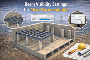
Why Beam Visibility Matters
Poor beam visibility can lead to several documentation issues. For example, plans may appear confusing, linework can overlap, and as a result, contractors may misinterpret drawings.
Proper visibility settings ensure clean, readable drawings.
Controlling Beam Visibility in Views
Visibility/Graphics Overrides
Access:
VG → Structural Framing
You can control:
-
Line weights
-
Line styles
-
Cut and projection appearance
Adjust these settings per view for clarity.
Using View Filters for Beam Control
Filters allow you to:
-
Highlight primary beams
-
Differentiate secondary beams
-
Hide specific beam types
This is extremely useful in large projects with complex framing.

Analytical Settings for Structural Beams
Analytical modeling is critical for structural analysis and coordination with engineering software.
Understanding Analytical Models
Each element includes an analytical representation used for load calculations, structural analysis exports, and connection verification. Therefore, proper alignment of this model is essential for accurate results. The analytical model must align correctly with columns and supports.
Adjusting Beam Analytical Alignment
You can control:
-
Analytical centerline
-
Vertical and horizontal offsets
-
Node connectivity
Misaligned analytical models can cause incorrect analysis results.
Showing or Hiding Analytical Models
Analytical models can be:
-
Shown in analytical views
-
Hidden in architectural views
-
Exported for structural analysis
Always verify analytical visibility before exporting models.
Common Mistakes in Beam Modeling (and How to Avoid Them)
Incorrect Beam Elevation
Always check:
-
Beam top and bottom offsets
-
Relationship to slab thickness
Overusing Manual Beams Instead of Systems
Beam systems reduce errors and save time. Use them whenever repetition exists.
Ignoring Analytical Settings
Analytical accuracy is just as important as visual accuracy.
Best Practices for Professional Beam Modeling
-
Always model beams on grids where possible
-
Use beam systems for repetitive framing
-
Verify beam visibility in every drawing view
-
Regularly check analytical alignment
-
Coordinate beams with slabs, columns, and ceilings
Following these practices improves model quality and reduces coordination issues.
Conclusion
Beams and beam systems play a foundational role in structural BIM modeling. Proper beam placement on grids, efficient beam system creation, and well-managed beam visibility and analytical settings lead to accurate models, clean drawings, and reliable construction documents.
Ultimately, mastering these techniques not only improves your Revit workflow but also enhances coordination with engineers, architects, and contractors. With consistent practice and attention to detail, you can produce professional-grade structural models that meet real-world construction standards.